Experimenting with a 32KB RAM
Monday, 4th August 2008
The next component I thought I'd experiment with is the RAM. The project is an analogue recorder - a circuit that samples an analogue input periodically and saves it in RAM, and can be configured to play the recorded signal back afterwards.
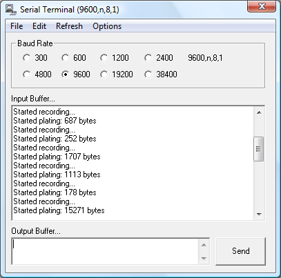
Yes, it says plating.
A single RAM chip offers 32K with an eight-bit word size. This requires fifteen lines to address it, A0..A14. The PICAXE-28X1 that is to control the circuit does not have enough output pins to be able drive this address bus and a data bus (to transfer values to and from RAM) and a still have enough pins left over to control the various components. To get around this, two octal (eight-bit) latches are used to drive the address lines, A0..A7 from one chip and A8..A14 from another. The inputs to these latches are connected to the data bus (PortC on the PICAXE), and two pins on the PICAXE are set aside to trigger the latch enable pins on either latch.
What this means in practice is that if you wished to change the current address to $1234 you would put $34 on the data bus and trigger the latch that corresponds to the least significant byte of the address, then put $12 on the data bus and trigger the latch that corresponds to the most significant byte of the address.
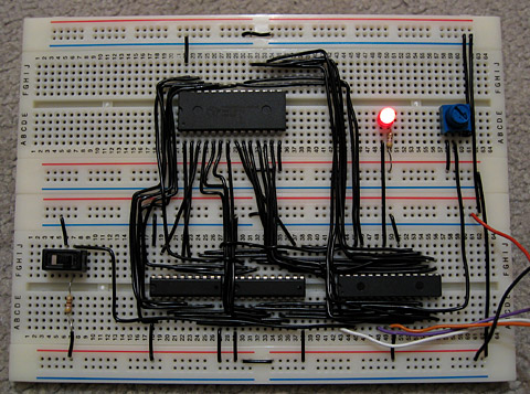
Any hobbyist can have wire insulation in any color that he wants so long as it is black.
A 10K potentiometer provides the required analogue input and an LED provides the output. The switch on the left is used to change between recording and playback modes. The large chip at the top is the RAM, the two small ones in the middle are the octal latches and the medium one on the right is the PICAXE-28X1.
As only 15 lines are needed to address 32KB, the most significant bit of the address bus is wired to the /WE pin of the RAM chip. This pin determines whether we're writing to (low) or reading from (high) the chip. This effectively means that addresses $0000..$7FFF are used when writing and addresses $8000..$FFFF are used when reading.
The only remaining connections to the RAM chip required are chip enable (/CE) and output enable (/OE). When chip enable is low, the RAM chip can be accessed; when high, it ignores all input. When not in use we therefore make sure that chip enable is high. When output enable is low, the RAM chip puts the value at the current address onto the data bus, so we need to pull this low when reading but make sure it's left high most of the time so that the RAM chip doesn't interfere with other devices trying to put a value on the data bus.
The code for the test program is as follows:
; Pins:
Symbol RamChipDisable   = 4
Symbol RamOutputDisable = 5
Symbol AddressLatch0    = 6
Symbol AddressLatch1    = 7

; Registers:
Symbol RamValue         = B0
Symbol RamAddress       = W1 ; B3:B2
Symbol RamAddressLow    = B2
Symbol RamAddressHigh   = B3
Symbol RamPointer       = W2 ; B5:B4

Symbol RecordingLength  = W3 ; B7:B6

Boot:
	Let DirsC = $00
	High RamChipDisable
	High RamOutputDisable
	Low AddressLatch0
	Low AddressLatch1
	Let RamPointer = 0
	SetFreq M8

Main:

StartPlaying:
	SerTxd ("Started playing: ", #RecordingLength, " bytes", CR, LF)
	Let RamPointer = 0
	Pause 100
PlayingLoop:
	If PortA Pin1 = 1 Then StartRecording

	; Read stored value from RAM.
	Let RamAddress = RamPointer
	GoSub ReadRam

	; Set LED brightness to stored value.
	Let W4 = RamValue * 4
	HPwm PwmSingle, PwmHHHH, %0100, 255, W4

	; Increment playback pointer and loop if hit end.
	Let RamPointer = RamPointer + 1
	If RamPointer = RecordingLength Then
		RamPointer = 0
	EndIf

	; Loop back.
	GoTo 	PlayingLoop


StartRecording:
	SerTxd ("Started recording...", CR, LF)
	Let RecordingLength = 0
	Pause 100
RecordingLoop:
	If PortA Pin1 = 0 Then StartPlaying

	; Read value from ADC.
	ReadAdc 0, RamValue

	; Set LED brightness to read value.
	Let W4 = RamValue * 4
	HPwm PwmSingle, PwmHHHH, %0100, 255, W4

	; Store value read from ADC into RAM.
	Let RamAddress = RecordingLength
	GoSub WriteRam

	; Increment record pointer.
	Let RecordingLength = RecordingLength + 1

	GoTo RecordingLoop

WriteRam:
	; Set up address bus:
	Let DirsC = $FF
	Let RamAddressHigh = RamAddressHigh & %01111111
	Let PinsC = RamAddressHigh
	High AddressLatch1 : Low  AddressLatch1
	Let PinsC = RamAddressLow
	High AddressLatch0 : Low  AddressLatch0
	; Set up data bus and write:
	Let PinsC = RamValue
	Low RamChipDisable
	High RamChipDisable
	Let DirsC = $00
	Return

ReadRam:
	; Set up address bus:
	Let DirsC = $FF
	Let RamAddressHigh = RamAddressHigh | %10000000
	Let PinsC = RamAddressHigh
	High AddressLatch1 : Low  AddressLatch1
	Let PinsC = RamAddressLow
	High AddressLatch0 : Low  AddressLatch0
	; Set up data bus and read:
	Let DirsC = $00
	Low RamOutputDisable
	Low RamChipDisable
	Let RamValue = Pins
	High RamChipDisable
	High RamOutputDisable
	Return
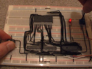
As before, there's a simple video of the circuit in action.
Back to Hardware
Friday, 1st August 2008
I enjoy dabbling with low-level programming, but have never actually built a computer to run these programs. I think it's time to correct that, and as the BBC BASIC project has required me to develop an almost complete Z80 OS (the only thing that's left for the TI-OS to do is manage files) I thought a Z80 computer would be a good start.
The planned specs are (as a starting point):
- 10 MHz Z80180 CPU;
- 64KB RAM (2 32K×8 SRAM chips);
- 128KB Flash ROM;
- Graphical LCD;
- Simple joypad input;
- Keyboard input (AT using either software AT routines or dedicated microcontroller).
The first spanner in the works is the Z80180, as I didn't read the datasheet closely enough and it's in a DIP 64 package with 0.07" pin spacing instead of the standard 0.1" pin spacing. I'll need to find some way of constructing an adapter so I can use it with my breadboards and stripboard. 
In the meantime, I've concentrated on the graphical LCD. I picked a 128×64 backlit graphical LCD for the princely sum of £16. It's very easy to control - you hook up it up to a 8-bit data bus to transfer image data and instructions and a handful of control pins to indicate what you're doing on that bus (reading or writing, whether you're sending an instruction or some image data, that sort of thing) and that's it - the only supporting circuitry it requires is a 10K potentiometer to act as a contrast control and power for the display and backlight.
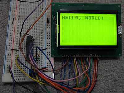
To experiment with the LCD, I'm using a PICAXE-28X1 microcontroller, programmed in BASIC. There isn't much space to store graphics, so I'm using a 32 character font (at eight bytes per character, that takes up all 256 bytes of free EEPROM space!)
; LCD data bus should be connected to port C.

Symbol LcdRegisterSelection = 0 ; D/I  :  4
Symbol LcdReadWrite         = 1 ; R/W  :  5
Symbol LcdStartEnable       = 2 ; E    :  6
Symbol LcdChipSelect1       = 3 ; CS1  : 15
Symbol LcdChipSelect2       = 4 ; CS2  : 16
Symbol LcdReset             = 5 ; /RST : 17

; Storage for console state variables.

Symbol ConsoleX             = B10
Symbol ConsoleY             = B11
Symbol ConsoleChar          = B12


	GoSub LcdInit                              ; Initialise LCD.
	B0 = %00111111 : GoSub LcdWriteInstruction ; Switch LCD on.

	GoSub LcdClear ; Clear LCD

	; Write the obligatory message to the LCD.

	ConsoleX = 0 : ConsoleY = 0

	ConsoleChar = $08 : GoSub LcdPutChar ; H
	ConsoleChar = $05 : GoSub LcdPutChar ; E
	ConsoleChar = $0C : GoSub LcdPutChar ; L
	ConsoleChar = $0C : GoSub LcdPutChar ; L
	ConsoleChar = $0F : GoSub LcdPutChar ; O
	ConsoleChar = $1D : GoSub LcdPutChar ; ,
	ConsoleChar = $00 : GoSub LcdPutChar ;
	ConsoleChar = $17 : GoSub LcdPutChar ; W
	ConsoleChar = $0F : GoSub LcdPutChar ; O
	ConsoleChar = $12 : GoSub LcdPutChar ; R
	ConsoleChar = $0C : GoSub LcdPutChar ; L
	ConsoleChar = $04 : GoSub LcdPutChar ; D
	ConsoleChar = $1B : GoSub LcdPutChar ; !

	Pause 2000

	B2 = 0
MainLoop:
	B2 = B2 - 1
	B0 = B2
	GoSub LcdGotoZ
	Pause 30
	GoTo MainLoop

LcdInit:
	DirsC = $00               ; Set data bus to input.
	High LcdStartEnable       ; We're not writing anything.
	High LcdChipSelect1
	High LcdChipSelect2
	Low LcdReset
	Pause 500
	High LcdReset
	Pause 500
	Return

LcdWriteInstruction:
	Low LcdReadWrite
	DirsC = $FF               ; Data bus = output.
	PinsC = B0                ; Set data bus state.
	Low LcdRegisterSelection  ; Instruction, not data.
	Low LcdStartEnable
	High LcdStartEnable
	DirsC = $00               ; Leave data bus floating.
	Return

LcdWriteData:
	Low LcdReadWrite
	DirsC = $FF               ; Data bus = output.
	PinsC = B0                ; Set data bus state.
	High LcdRegisterSelection ; Data, not instruction.
	Low LcdStartEnable
	High LcdStartEnable
	DirsC = $00               ; Leave data bus floating.
	Return

LcdGotoX:
	B0 = B0 And 7
	B0 = B0 + %10111000
	GoTo LcdWriteInstruction

LcdGotoY:
	B0 = B0 And 63
	B0 = B0 + %01000000
	GoTo LcdWriteInstruction

LcdGotoZ:
	B0 = B0 And 63
	B0 = B0 + %11000000
	GoTo LcdWriteInstruction

LcdClear:
	For B2 = 0 To 7
		B0 = B2
		GoSub LcdGotoX
		B0 = 0
		GoSub LcdGotoY
		B0 = 0
		For B3 = 0 To 63
			GoSub LcdWriteData
		Next
	Next B2
	Return

LcdPutMap:
	B1 = B0 * 8
	For B2 = 0 To 7
		Read B1, B0
		GoSub LcdWriteData
		B1 = B1 + 1
	Next B2
	Return

LcdPutChar:
	B0 = ConsoleY
	GoSub LcdGotoX
	B0 = ConsoleX * 8
	If B0 < 64 Then
		Low LcdChipSelect2
	Else
		Low LcdChipSelect1
		B0 = B0 - 64
	EndIf
	GoSub LcdGotoY
	B0 = ConsoleChar
	GoSub LcdPutMap
	High LcdChipSelect1
	High LcdChipSelect2
	ConsoleX = ConsoleX + 1
	If ConsoleX = 16 Then
		ConsoleX = 0
		ConsoleY = ConsoleY + 1
		If ConsoleY = 8 Then
			ConsoleY = 0
		EndIf
	EndIf
	Return

; Font
EEPROM $00,($00,$00,$00,$00,$00,$00,$00,$00,$7E,$7F,$09,$09,$7F,$7E,$00,$00)
EEPROM $10,($7F,$7F,$49,$49,$7F,$36,$00,$00,$3E,$7F,$41,$41,$63,$22,$00,$00)
EEPROM $20,($7F,$7F,$41,$63,$3E,$1C,$00,$00,$7F,$7F,$49,$49,$49,$41,$00,$00)
EEPROM $30,($7F,$7F,$09,$09,$09,$01,$00,$00,$3E,$7F,$41,$49,$7B,$3A,$00,$00)
EEPROM $40,($7F,$7F,$08,$08,$7F,$7F,$00,$00,$41,$41,$7F,$7F,$41,$41,$00,$00)
EEPROM $50,($20,$61,$41,$7F,$3F,$01,$00,$00,$7F,$7F,$1C,$36,$63,$41,$00,$00)
EEPROM $60,($7F,$7F,$40,$40,$40,$40,$00,$00,$7F,$7F,$06,$1C,$06,$7F,$7F,$00)
EEPROM $70,($7F,$7F,$0C,$18,$7F,$7F,$00,$00,$3E,$7F,$41,$41,$7F,$3E,$00,$00)
EEPROM $80,($7F,$7F,$09,$09,$0F,$06,$00,$00,$3E,$7F,$41,$31,$6F,$5E,$00,$00)
EEPROM $90,($7F,$7F,$09,$19,$7F,$66,$00,$00,$26,$6F,$49,$49,$7B,$32,$00,$00)
EEPROM $A0,($01,$01,$7F,$7F,$01,$01,$00,$00,$3F,$7F,$40,$40,$7F,$3F,$00,$00)
EEPROM $B0,($1F,$3F,$60,$60,$3F,$1F,$00,$00,$7F,$7F,$30,$1C,$30,$7F,$7F,$00)
EEPROM $C0,($63,$77,$1C,$1C,$77,$63,$00,$00,$07,$0F,$78,$78,$0F,$07,$00,$00)
EEPROM $D0,($61,$71,$59,$4D,$47,$43,$00,$00,$00,$00,$5F,$5F,$00,$00,$00,$00)
EEPROM $E0,($02,$03,$59,$5D,$07,$02,$00,$00,$00,$80,$E0,$60,$00,$00,$00,$00)
EEPROM $F0,($00,$00,$60,$60,$00,$00,$00,$00,$07,$07,$00,$07,$07,$00,$00,$00)
The code isn't very robust - it doesn't check the state of the LCD's busy flag as I'm assuming that a 4MHz PIC running an interpreted BASIC is too slow to manage to write another byte to the LCD driver before it has finished processing the last one.
The font was generated from the following image (it's the BBC Micro font):

It's rotated through 90° as, unlike the LCD driver in the TI-83+, each byte written outputs 8 pixels vertically, with the least significant at the top. (On the TI-83+, each byte written outputs 8 pixels horizontally, with the most significant bit on the left). More interestingly, this graphical LCD is made up of two 64×64 regions next to eachother, and by controlling two chip select pins you can control whether each byte written updates the left side, the right side, neither or both. I'm entirely sure how I could use this, though, other than not-very-exciting tricks like clearing the LCD extra-fast.
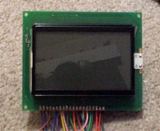
Finally, here's a video of the LCD test in action. It's not very speedy, but will hopefully pick up some speed once I figure out how I'm going to use that Z80180 CPU.
Graphical text, BASIC tokeniser and flood-filling
Tuesday, 29th July 2008
I've got a fairly hackish "graphical text" mode set up (enabled with VDU 5, disabled with VDU 4) that causes all text that is sent to the console to be drawn using the current graphics mode (at the graphics cursor position, using the graphics colour and logical plotting mode and graphics viewport). This allows text to be drawn at any position on-screen, but is (understandably) a bit slower and doesn't let you do some of the things you may be used to (such as scrolling text, copy-key editing and the like).

I've also done some work on a tool to convert files from the PC to use in BBC BASIC. It takes the form of a Notepad-like text editor:
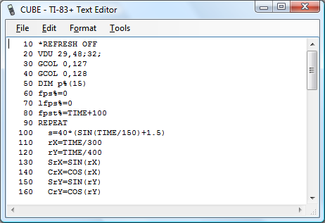
BBC BASIC programs are stored in a tokenised format (usually .bbc files on a PC) and need to be wrapped into a .8xp for transferring to the calculator. The editor above can open .8xp, .bbc and .txt directly, and will save to .8xp.
The detokeniser can be passed a number of settings, which can be used to (for example) generate HTML output, like this. The indentation is generated by the detokeniser (leading/trailing whitespace is stripped by the tokeniser). The tool can also be used to directly convert binaries into .8xp files if need be.


I've been doing a little work on a flood-filling algorithm. (PLOT 128-135, 136-143). The above images show its progress; on the left is the first version (which can only fill in black). There is a hole in the bottom-left of the shape, so the leaking is intentional. It also stops one pixel away from the screen boundary -- this too is intentional (it clips against the viewport). The second version, in the middle, plugs the leak and applies a pattern (which will be a dither pattern in BBC BASIC) to the filled area. On the right is the third version, which will fill over black or white pixels with a pattern.
The main filling algorithm needs a 764 byte buffer for the node queue and three 16-bit pointer variables to manage the queue. I've rounded the queue size up to 768 bytes, so it fits neatly on one of the RAM areas designed to store a bitmap of the display.
The problem is filling with a pattern. The way I currently do this is to back up the current screen image to a second 768-byte buffer, fill in black as normal, then compare the two buffers to work out which bits have been filled and use those as a mask to overlay the dither pattern. This is quite a lot of RAM, just to flood-fill an image!
For those who are interested, I'm using the "practical" implementation of a flood fill algorithm from Wikipedia.
Text viewports and sprites
Monday, 21st July 2008
Back to work on the TI-83 Plus port of BBC BASIC! To complement the graphics viewport I've added support for text viewports — this lets you define the area the text console uses. The following VDU commands are now supported:
- VDU 24,<left>;<top>;<right>;<bottom>;
Define a graphics viewport. - VDU 28,<left>,<top>,<right>,<bottom>
Define a text viewport. - VDU 26
Reset both viewports to their default settings (full screen). - VDU 29,<x>;<y>;
Defines the graphics origin.

The above screenshots defines the graphics viewport to fill the left hand side of the screen and shunts the text viewport over to the right half, using the following code:
VDU 24,0;0;47;63;
VDU 28,12,0,23,9
VDU 29,24;32;
I've also added simple sprite drawing to BBC BASIC's PLOT command. PLOT usually takes a shape type and two coordinates, but for sprites (shapes 208..215) I've added an extra parameter - the address of the sprite data to use.

   10 DIM ball 7
   20 ball?0=&3C
   30 ball?1=&5E
   40 ball?2=&8F
   50 ball?3=&DF
   60 ball?4=&FF
   70 ball?5=&FF
   80 ball?6=&7E
   90 ball?7=&3C
  100 *REFRESH OFF
  110 REPEAT
  120   CLG
  130   T=TIME/100
  140   FOR P=0 TO 5
  150     A=P/3*PI+T
  160     X=16*SIN(A)+44
  170     Y=16*COS(A)+28
  180     PLOT 213,X,Y,ball
  190   NEXT
  200   *REFRESH
  210 UNTIL INKEY(0)<>-1
  220 *REFRESH ON
The above code allocates 8 bytes of memory (DIM ball 7) then copies the sprite data to it by use of the ? indirection operator. This is a little laborious, so in reality you'd probably store your sprites in a binary file external to the main program, and might load them like this:
   10 ball%=FN_loadSprite("SPRITES",0)
   20 face%=FN_loadSprite("SPRITES",1)
   30 *REFRESH OFF
   40 REPEAT
   50   CLG
   60   T=TIME/100
   70   FOR P=0 TO 5
   80     A=P/3*PI+T
   90     X=16*SIN(A)+44
  100     Y=16*COS(A)+28
  110     PLOT 213,X,Y,ball%
  120   NEXT
  130   PLOT 213,44,28,face%
  140   *REFRESH
  150 UNTIL INKEY(0)<>-1
  160 *REFRESH ON
  170 END
  180 DEF FN_loadSprite(f$,i%)
  190 fh%=OPENIN(f$)
  200 PTR#fh%=i%*8
  210 DIM spr 7
  220 FOR j%=0 TO 7
  230   spr?j%=BGET#fh%
  240 NEXT j%
  250 CLOSE#fh%
  260 =spr
  270 ENDPROC
(Note FN_loadSprite() at the end of the program). The result is the following:

Next up: drawing text at the graphics cursor position (as sprites).
XNA DOOM3
Thursday, 3rd July 2008
This journal is starting to look a little drab, so here's a splash of colour.
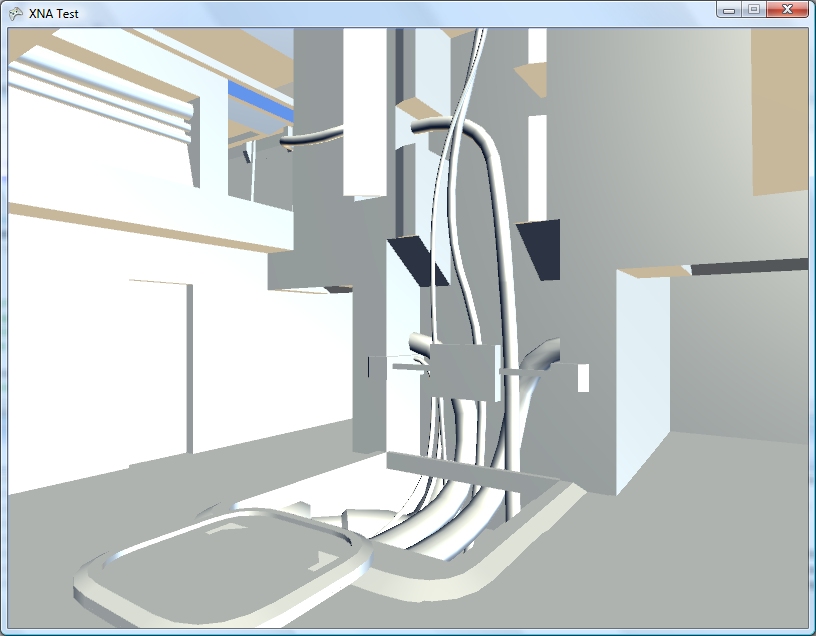
Not really all that colourful, on second thoughts. I fancied a short break from BBC BASIC, and seeing that the current XNA CTP supports VS 2008 I thought I'd try a bit more work on hardware-accelerated 3D. I've never worked with shadows, bump mapping or visibility portals, and have a copy of DOOM 3, so thought that would provide a nice set of resources to experiment with.
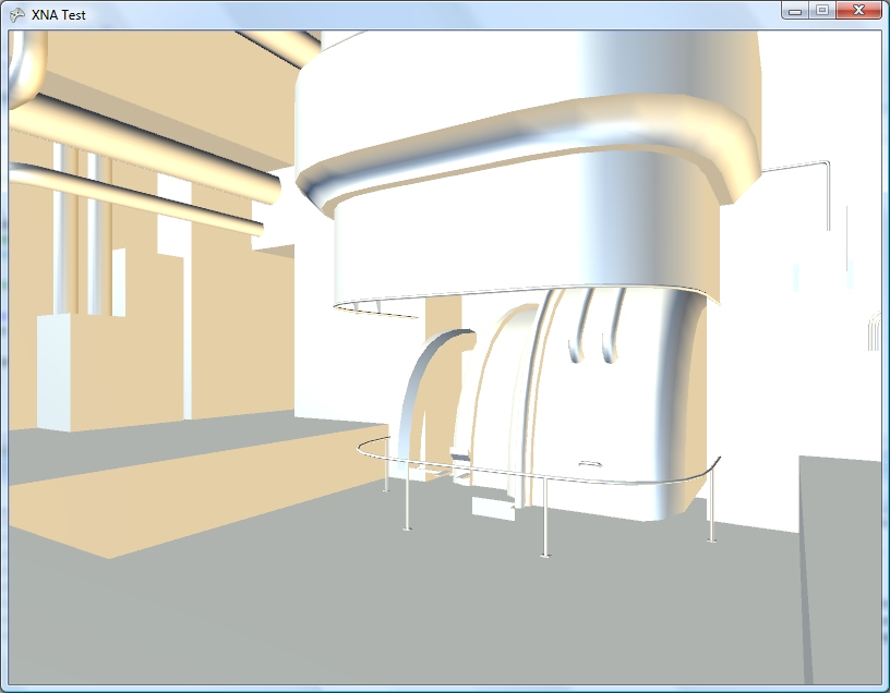
The screenshots are generated by simply brute-force rendering of all surfaces of all models in a level (.proc) file. The odd colours and lighting are courtesy of the default lighting provided by the BasicEffect class. The level files are simple to parse (they're just text files breaking each surface down into vertex and index arrays, ready to be fed to the video hardware), so though I've not found much documentation on them it's been pretty easy to guess what's what so far.
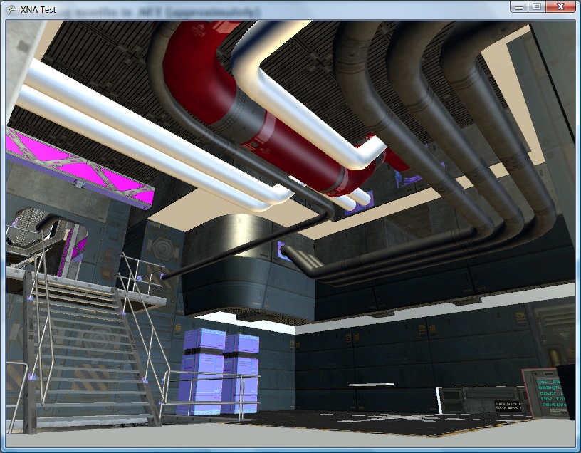
The above textures are loaded by taking the material name and appending .tga, which seems to return a random mixture of specular, diffuse or normal maps. There is a materials directory that appears to contain definitions for which image file to use for each different type of texture map, so that looks like the next thing to investigate.